Master's Thesis
( 2016 )
Open-source Toolkit ( OSTK ) for real-time CNC control
Tisch's Interactive Telecommunications Program ( ITP ), the program from which I attained my Master's degree, provided me with a plethora of incredible tools with which I was able to fully explore my creativity and bring to fruition numerous speculative project ideas. These tools for fabrication included laser-cutters, 3D printers and 3-axis mills. I was fortunate, given my training as an Industrial designer, that I was taught the skills necessary to take full advantage of these machines; in particular certain design and 3D CAD (computer-aided design) software packages. However, the barrier for entry for taking full advantage of these machines is still relatively high. Users often need to learn complex design software packages necessary for generating content, along with the fact that most machines make use of proprietary firmware - limiting the use of the machines to the software shipped with them. My graduate thesis project focused on lowering this barrier for entry, and making the hardware and software more available to the everyman by opensourcing it. The final project consists of an open-source design for 2-axis pen plotter, custom communication protocol for controlling it, as well easy-to-use software with a simple graphical user intefrace ( GUI ).
The code is on GitHub.
The project is also located in the ITP Archive.
Technology Stack
Solidworks, Cinder, C++, MakerBot Replicator 2, Epilog Laser Cutter, EagleCad, OtherMill
THESIS FINAL PROJECT PRESENTATION:
The video shown below is a recording of my final thesis project presentation. We were required to present the overarching concept and outline our process in a 10 minute presentation that was streamed lived over the internet. The presentation includes a live demo of the plotter in action. This video may quite possibly be a case of TL;DR, so the important points are broken out and outlined in the sections that follow.
BACKGROUND:
Computer Numerical Control ( CNC ) is a communication protocol used for interfacing with machinery used for fabrication; machines like 3D printers, laser cutters, routers and mills. These can be, and often are, referred to using the generic term 'CNC machines'. Traditionally a 2D or 3D file is created using a piece of computer-aided design ( CAD ) software, and is then converted into a set of machine-readable instructions before the part can be produced. These instructions are then executed by the machine making use of the aforementioned CNC protocol. The problem with this, in my opinion, is that it offers no form of interaction - there is no feedback loop. As such, my thesis project explored the idea of using the familiar metaphor of drawing as the primary method of interaction, meaning no prior expertise or knowledge of software was required to operate the machine; only the ability to hold a pen.
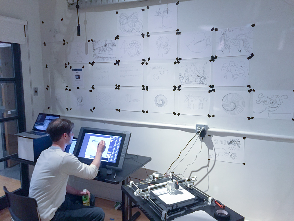
I designed and built a custom 2-axis pen plotter to demonstrate and explore this idea. This would allow me to write my own software, along with my own communication protocol. There were several motivating factors behind the decision to do this, namely: I wouldn't have to spend a relatively large sum of money to procure such a machine, I wouldn't be limited to the software with which it's intended to be used, and I'd have full control over the user-interaction.
INTERFACE DESIGN and USER-INTERACTION:
The main motivator for doing this project was creating a mode of interaction that would allow anyone, even a child, to control a CNC machine ( and in this case, for the purpose of demonstration, a simple 2-axis pen plotter ). This is the precise reason I selected drawing as my metaphor for interaction, as it's a skill we're all taught at a very early age. By making use of a drawing tablet and stylus, I could take the user's pen strokes as digital input and send those, in real-time, to the plotter. I wanted to focus on an interface that was simple, uncluttered, and similar enough to existing digital drawing and design applications such as Adobe Illustrator. I used Cinder, a C++ framework for creative coding, to build the application - making use of the fantastic ImGui library for the design of the interface.

Screenshot of the prototype Graphical User Interface ( GUI ) showing three simple tools: the pencil, the line, and the circle.
The majority of user-testing took place at ITP's annual Spring Showcase. The event is open to the public and provides students with a good platform for displaying their work, a well as gathering valuable feedback from users not necessarily very familiar with the technology involved. I setup a Wacom Cintiq tablet alongside the plotter and allowed people to use the application to explore the interface without any instructions. The images below were collected over the two days of the showcase.


SOFTWARE DESIGN, HARDWARE and COMMUNICATION PROTOCOL:
I owe a great debt of gratitude to Brian Schmalz, the designer of the EiBotBoard ( sold by EvilMadScientist ) - the motor control board I used for the plotter. He graciously donated his time to help me debug portions of the code and troubleshoot problems with the design of my communication protocol.

The EiBotBoard v2.0, the motor control board for the plotter
The EiBotBoard hardware consists of a PIC18F46J50 microcontroller and two Allegro A4983 stepper drivers, along with some voltage regulators and USB connection hardware. It interfaces with the custom software I wrote via the Serial Port and communicates over USB. The EiBotBoard's firmware is designed to take string commands using serial communication ( the process of sending data sequentially bit by bit over a single channel ).
The key to the real-time control of the plotter lay in the call-and-response communication style. Sending too many sequential commands over Serial to the EiBotBoard caused the buffer to overflow, which in turn lead to several commands failing to execute. The custom protocol waits for a response from the EiBotBoard before sending the next command off of the top of the 'queued commands' stack. Adding complications to this process was the fact that the software had to send commands to the limit switch for each axis to ensure that the gantry was in the correct position. Because every command is executed synchronously, this meant that waiting for the response from each limit switch had to be carefully managed before sending any movement commands.
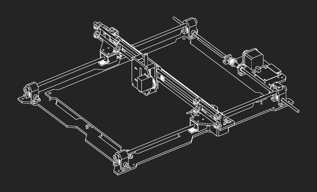
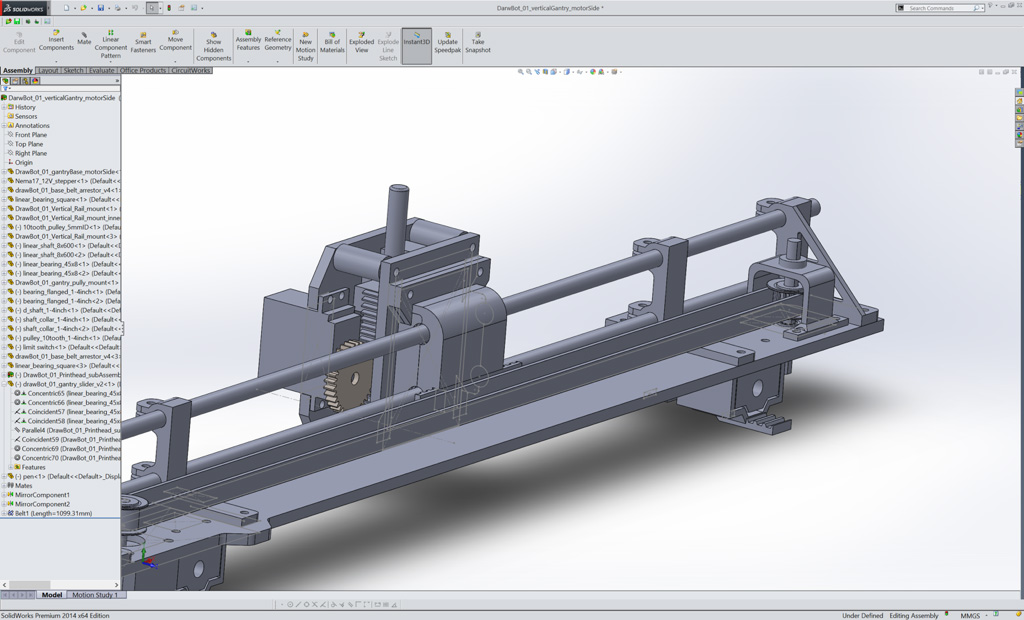
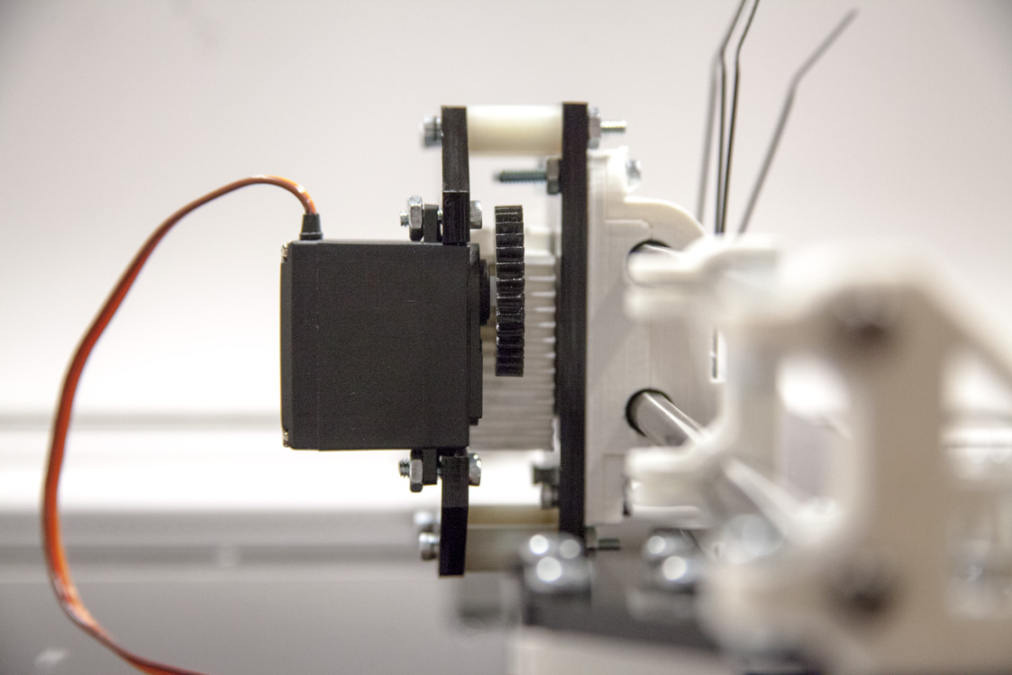
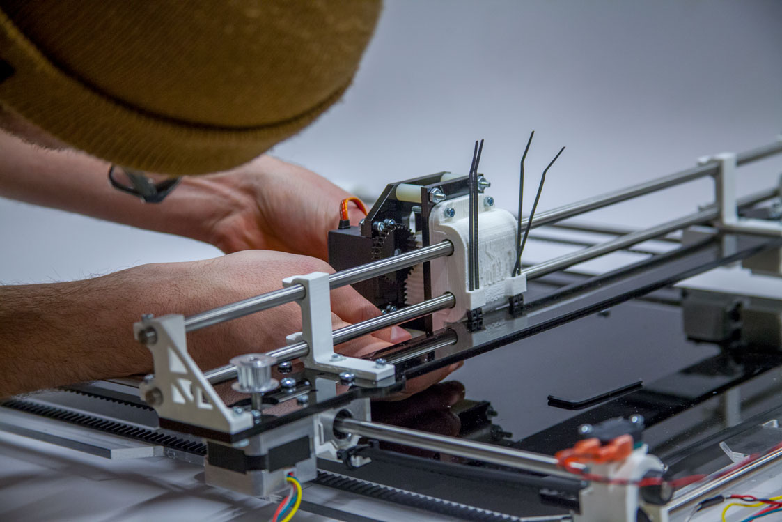
PLOTTER DESIGN AND FABRICATION:
Prior to coming to ITP my focus was design-for-fabrication, so I spent a great deal of time using CAD packages like Solidworks. This experience allowed me to design parts in 3D, create virtual assemblies, and finally produce 2D DXF files for laser-cutting acrylic and 3D printable STL files. I sourced all the mechanical components from ServoCity, a truly fantastic resource for any hobbyist or maker looking to build anything that moves. The best part being that they offer downloadable versions of all of the parts they offer, meaning I could include them in my virtual assembly and design my own components around them. This became a crucial part of my design workflow.
ADDITIONAL FEATURES:
Although the plotter was designed primarily to showcase the real-time control aspect of the interaction, I wanted to include additional features in the software - both in order to channel myself, but also to not limit the functionality and machine's flexibility. I created two additional 'modes', or features, within the GUI. The first allows the user to capture an image of themselves using the computer's webcam, and uses a custom stippling algorithm to generate a dot-matrix-style print. The second feature, given the open-source nature of the software, allows a more knowledgeable user to manipulate the source code and generate patterns algorithmically that can then be executed by the plotter.

